Summary of Features
The Non-Contact Magnetic Tomography pipeline survey technology enables the survey of pipelines of all configurations,underground and submerged, while they remain working at normal operating pressures and without the preparation
procedures needed by in-line intelligent pig techniques.
© Transkor Asia
Main Features Page 1
•Assessment of defects is based not on geometry but of the level of stress caused by them.• Data is collected by a non-contact scanning magnetometer and is subsequently analysed by a patented software.
• The pipeline remains in service throughout the survey thus eliminating cleaning, purging and downtime costs.
• The survey report defines the location and extent of geometric and corrosion defects including:
º Dents, corrugations, scores, out of roundness and differences in wall thickness
º Loss of metal – including internal and external corrosion defects of any nature.
º Delamination
º Defects within welded joints eg cracks, pores, lack of weld penetration, displacement of edges and metal flakes
º Crack-like defects in any orientation
º Sections with deviations of a level of stress deformed conditions caused by, for example, sagging, landslips, washouts or transitions under roads.
º Local corrosion under scaled insulating coating
© Transkor Asia
Main Features Page 2
• The location of defects are defined within an accuracy of +/- 1.5m thus facilitating further investigation or repair.• The final report defines the degree of danger of defects and recommends maximum safe working pressures and also the length of time it is safe to operate defective sections of pipe at those pressures.
• The system can be used to survey trunk pipelines (across any terrain including water) and service pipelines within cities. Accuracy is not affected by either the close proximity of other pipelines or city traffic
© Transkor Asia
Non-Contact Scanning Magnetometer
Specification:
Wall thickness measurement range | From 3mm (maximum is not limited) |
| Pipeline diameter D restrictions | 56 ≤ D ≥ 1420 mm |
| Speed range | 2-5 m/s |
| Maximum pipeline pressure | Unlimited |
| Minimum pipeline pressure | 0.02 MPa |
| Minimum turning radius of pipe | Unlimited |
| Minimum inside diameter of pipe | Unlimited |
| Overall dimensions of magnetometer | 200×200×750 mm |
| Magnetometer Mass | 4.7 kg |
| Minimum length of a pipeline required for one pass | Unlimited and does not depend on seasons or pipeline condition |
| Completeness of the control along the extent of installation | 100 % |
| Admissible deviation from the pipeline axis | On distance not more than 3 x D (D = pipeline diameter) |
| Admissible distance between the magnetometer and the pipeline | 20 x D |
| Maximum measurement step frequency along the longitudinal axis | 0.25 m |
| Anomaly positioning accuracy | ± 1.5 m |
| Accuracy of angular location of anomalies | ± 20” |
| Error of odometer (distance transducer) | Not more than 5 % |
Magnetic Data Collection & Analysis
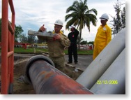
Fluctuations in magnetic field strength are used to automatically display, register and record in memory defects in the metal as the magnetometer is carried along the longitudinal axis of the pipeline by an operator. All data is then subsequently analysed to produce an integrated indicator of the hazard level of the defects detected. This is presented in chart form and references an identification of each defect and its location (obtained using GPS).
Flaws in the metal are located by relating the magnetic permeability of the pipeline to stress raisers and are defined by analysing the interconnection of stress concentration with a change in the polarity of the components of the earth’s magnetic field.
The effect of interfering fields is minimised by equipping the magnetometer with high sensitivity converters and dedicated software with filtration algorithms.
© Transkor Asia
Identifiable Defects Page 1
The following internal and external defects, their parameters and their location can be accurately defined:
• Crack-like defects in any orientation (laps, scabs, scratches, stress corrosion, cracking and exfoliation)
• Weld defects (laps, pores, cracks, lack of fusion, lack of penetration, displacement, metal flakes, residual thermal stress within the heat affected zone)
• Compression marks, corrugations, scores, out of roundness and changes in wall thickness caused by corrosion pits and filiform corrosion
• Loss of metal – including internal and external corrosion defects of any nature
• Delamination
• Sections with deviations of a level of stress deformed conditions caused by, for example, sagging, landslips, washouts or transitions under roads.
• Local corrosion under scaled insulating coating
• Indents
• Buckles
• Deviation from the specified laying axis
© Transkor Asia
Identifiable Defects Page 2
Tolerance and Accuracy
Minimum length of detectable defects: >10mm
Opening of detectable defects: >300 microns
Depth of detectable defects: >5% of the pipe wall thickness
Measurement tolerance:
Crack length: +/-20%
Crack depth: +/- 30%
Wall thickness loss: <25%
Detection rate: 2m/sec max
Location and orientation of defects: No restriction
Process Limitations
Operating temperature: None defined. Has been used at -50 to + 63 deg C
Pipeline diameter: Min 56mm
Max 1420mm
(based on actual survey experience to date. Extensions to either stated limit may be possible)
Pipe wall thickness: Min 2.8mm
Max 22mm
(based on actual survey experience to date. Extensions to either stated limit may be possible)
Detection rate: 2m/sec max
Distance between magnetometer and pipeline: 15 x pipe dia max (refers only to measuring pipeline depth and axis deviation)
Cannot guarantee the detection of those defects which do not cause a change in the level of stress deformed condition – ie blow holes, pitting
© Transkor Asia
Summary of Procedure
1. Analysis of pipeline design, executive and operational documentation
2. Visual inspection of the pipeline route
3. Preparatory works
4. Pipeline magnetic profile data collection
5. Data processing
6. Assess technical condition of pipeline
7. Mark out and excavate calibration pits
8. Additional NDT on exposed pipe in calibration pits
9. Finalise results, conclusions and presentation of report
© Transkor Asia
Experience
Launched commercially in 2002 the technology has to date been used to successfully survey more than 20,000km of subterranean and submerged pipelines in the Russian Federation, Uzbekistan, Ukraine, Syria, Argentina, Brazil, Colombia, Mexico, Croatia, Saudi Arabia, Malaysia, Indonesia, China, UK and the USA. Monitoring throughout this period has demonstrated an efficiency rate and reliability level of not less than 87% .© Transkor Asia